Over on YouTube user ElPaso TubeAmps has uploaded a video showing his transit/receiver relay system that allows a "boat anchor" (old radio) ham radio transmitter and SDRplay SDR receiver to coexist. In order to protect the SDRplay's front end from being destroyed by a ham radio transmitting on the same antenna, a relay should be used to ground the SDRplay during a ham radio transmission. He writes:
How to build a small chassis and relay system to switch the antenna from the SDR input to ground and open the speaker connection from the PC to the speakers during transmit. I use "boat anchor", i.e. separate VFO for transmitter and receiver equipment and this video is about that type of connection and is not for transceivers.
SDRPlay, RTL-SDR, Transmit-Receive , PC Speaker, T/R Switch
Steve Andrew, the author of the SDRplay Spectrum Analyzer software has recently released an update which enables several new features. This software allows you to use SDRplay SDRs to scan a wide swath of bandwidth by rapidly scanning in 10 MHz (or less) chunks over the SDRplay's frequency range. The SDRplay team write:
We are pleased to announce the availability of V1.0a of the Spectrum Analyser software developed by Steve Andrew specifically for the RSP line of products. This is a very-much upgraded version of the original alpha release and includes many new features as well as removing the limitations imposed on the previous version. New features include multiple traces, a versatile marker system with maths, peak find and display functions, Zero or non-Zero IF options and an upgraded tracking generator system. Currently support are:
At this years Hamvention Chris Howard from ICQ Amateur interviewed Andy at the SDRplay booth. In the interview they discuss various new features and improvements to SDRuno, the official software for SDRplay devices.
Later they also discuss the RSPduo, and the new diversity feature coming in a new version of SDRUno that is due to be released in a few weeks. The diversity feature works with the two tuners on the RSPduo to combine or subtract signals from two different antennas. Andy notes that diversity should be able to achieve a net 3dB increase in SNR, and is most useful for a moving or dynamic signal environment.
Finally Andy discusses the future development of SDRUno and notes that they're working on a plugin environment which will allow the creation of third party demod/decoders, a multiplatform server for remote SDR, and eventually cross platform drivers and SDRUno.
SDRPlay Announce Update to SDRUno and Future Plans for Software Defined Radio at Hamvention 2019
Over on his YouTube channel SignalsEverywhere, Corrosive has just released a new video titled "Software Defined Radio Introduction | What SDR To Buy? | Choose the Right one For You". The video is an introduction to low cost software defined radios and could be useful if you're wondering which SDR you should purchase.
The video includes a brief overview of the Airspy, KerberosSDR, PlutoSDR, LimeSDR Mini, HackRF, SDRplay RSPduo and various RTL-SDR dongles. In addition to the hardware itself Corrosive also discusses the compatible software available for each SDR.
Software Defined Radio Introduction | What SDR To Buy? | Choose the Right one For You
The SDRplay RSPDuo is a 14-bit dual tuner software defined radio capable of tuning between 1 kHz - 2 GHz. It's defining feature is that it has two receivers in one radio, which should allow for interesting phase coherent applications such as diversity.
In the latest v1.32 release of SDRUno a diversity feature has been added. Diversity reception was demo'd back in May at Hamvention, and we have a previous post with video about that. Diversity works by subtracting or adding two signals from the two receivers running independent antennas. The result is an up to 3 dB increase in SNR, and better performance with fading signals. They write:
From V1.32 onwards, MRC (Maximal Ratio Combining) Diversity is supported using the RSPduo. MRC Diversity can be used to combine the 2 tuner input streams together to potentially improved the SNR (signal to noise ratio). The same frequency is used for both tuners in the RSPduo and the gain can be adjusted either on each tuner independently or locked together (the default method).
Diversity mode is enabled by clicking on the RSPduo MODE dropdown and select DIVERSITY. Make sure both the 50 ohm ports are connected to the correct input source and note that the HiZ port is not available for Diversity mode. Trying to use the HiZ port will result in an error message being displayed.
SDRPlay have recently published a video demonstrating how the new RSPduo diversity feature in SDRUno can be used to cancel local interference. The SDRplay RSPDuo is a 14-bit dual tuner software defined radio capable of tuning between 1 kHz - 2 GHz. It's defining feature is that it has two receivers in one radio, which should allow for interesting phase coherent applications such as diversity. The RSPDuo's diversity feature allows us to either combine two antenna signals together for an up to 3 dB increase, or for removal of an unwanted noise source via subtraction of signals.
In the video they show a broadcast AM signal that has it's SNR reduced by being on top of a local electrical noise source. The use a Bonito Mega-dipole on tuner 1, and a Bonito Mini-whip on tuner 2. The Mini-whip appears to receive the local interference stronger, so can be subtracted away from the Mega-dipole's signal with the diversity function. The result is improved SNR, and the noise is almost entirely cancelled.
There are 2 very practical applications for diversity software. The first is MRC (Maximum Ratio Combination) Diversity which, in order to be effective, needs two antennas presenting the same signal with some degree of diversity. Then there is this second impressive application which is becoming more and more useful due to the growing number of domestic sources of interference.
This is possible in an RSPduo, due to the coherent nature of the combined tuner streams being presented to the computer for processing.
Using Diversity in SDRplay's SDRuno to Cancel Local Interference
The SDRplay team have posted some more videos that demonstrate the SDRplay Duo's diversity function. The SDRplay RSPDuo is a 14-bit dual tuner software defined radio capable of tuning between 1 kHz - 2 GHz. It's defining feature is that it has two receivers in one radio, which allows us to combine the signal from two antenna together.
In the video Jon uses a Wellbrook Magnetic Loop antenna and a Bonito Miniwhip antenna both connected to the RSP Duo. Individually each antenna receives the signal relatively poorly and fades in and out as conditions and signal reflections fluctuate. However, with diversity enabled the SNR is improved and fading is significantly reduced.
The method they use to combine signals is a relatively simple method called maximum-ratio combining (MRC). The idea is that the two signal channels are added together, with the currently stronger and less noisy channel having increased gain. So while the signal levels fluctuate, as long as one antenna can receive the signal you will see no fading.
SDRplay HF Diversity Demo
SDRplay note that the key to a good setup is to have the antennas spaced out at a quarter wavelength of the signal frequency that you are receiving. In a second video they show how to properly set up an antenna system for proper HF diversity receiving.
This video demonstrates how SDRuno diversity and the RSPduo can bring enhanced reception at HF using 2 antennas separated by approximately a quarter wavelength. It uses the the current version of SDRuno (V 1.32) and the dual tuner RSPduo SDR from SDRplay.
In this experiment we had a wire dipole with one leg approximately a quarter wavelength from a Boniwhip vertical - both were picking up similar strength signals before going into "diversity" (max ratio combination) mode.
The benefits of diversity tuning at HF are very dependent on many variables, most notably the changing nature of the reflected signal path and the degree to which noise and unwanted signals are not as coherent as the wanted signal.
Antenna and SDRplay set-up for HF diversity reception (rev1)
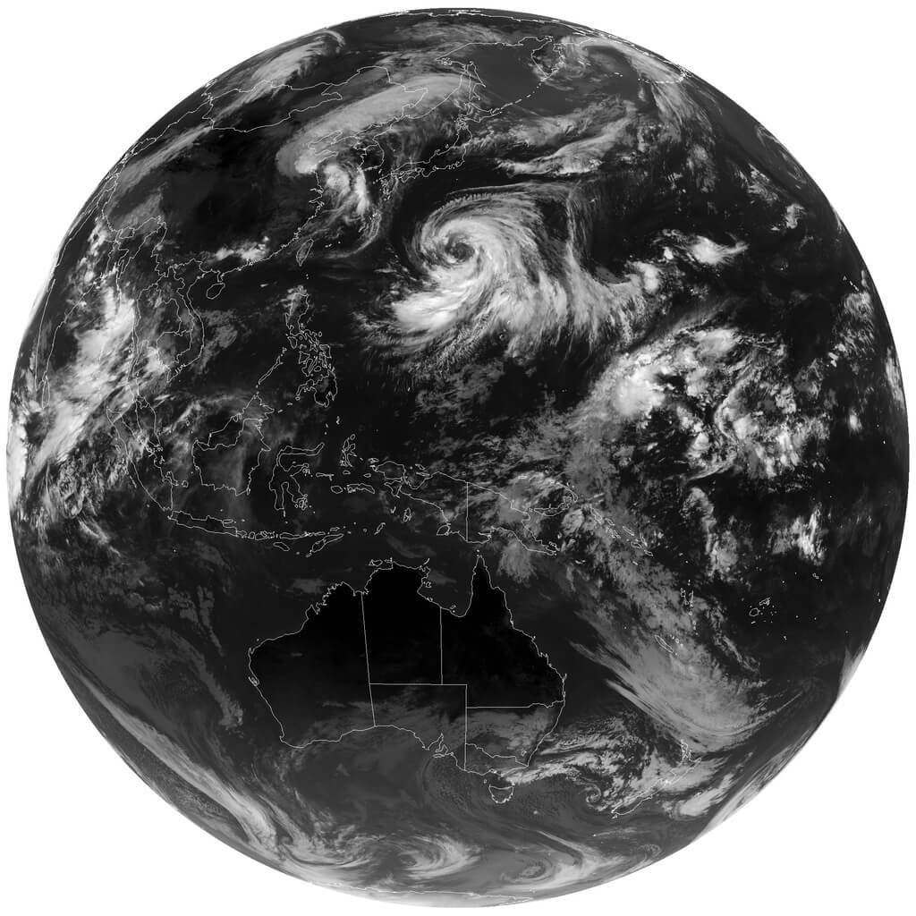
GOES 16/17 and GK-2A are geosynchronous weather satellites that transmit high resolution weather images and data. In particular they are far enough away from the earth to be able to take beautiful 'full disk' images which show the entirety of one side of the Earth. As these satellites are in a geosynchronous orbit, they can be counted on to be in the same position in the sky at all times, so no tracking hardware is required and images can be pulled down constantly throughout the day without having to wait for a polar orbiting satellite to pass over like you would with the NOAA APT or Russian Meteor satellites.
With a low cost WiFi grid dish antenna, LNA and RTL-SDR dongle, any home user within the footprint of one of these weather satellites can receive and decode live images directly from the sky. Setting up a station is overall not too difficult, but it can be a bit fiddly with a number of steps to complete. Below is our comprehensive guide. We'll show how to set up a self contained Raspberry Pi based system with goestools (free), as well as a guide for the Windows PC software XRIT decoder (US$125).
We've attempted to make the tutorial as newbie friendly as possible, but we do need to assume basic RF knowledge (know what antennas, SDRs, coaxial, adapters etc are), basic Linux competency for the goestools tutorial (using the terminal, using nano text editor), and basic Windows competency for the XRIT decoder tutorial (unzipping, editing text files, running programs).
A full disk false color image received directly from the GOES-17 satellite with an RTL-SDR. Click for the full size image (14MB).
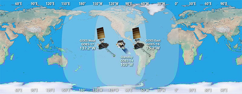
There are two fourth generation NOAA GOES satellites that are currently active, GOES-16 and GOES-17. These transmit HRIT signals, and also transmit shared data from the older third generation GOES 15, and Japanese Himiwari8 satellites. At the moment GOES-16 and GOES-17 are producing full disk images every 30 minutes, and close up "mesoscale" shots of the USA every ~15 minutes. GOES-16 (aka GOES-R) and GOES-17 (aka GOES-S) are also known as GOES-EAST and GOES-WEST respectively. At least one of these satellites can be received from North/South America, Canada, Alaska/Hawaii, New Zealand, Eastern Australia and some pacific islands.
There is also the older generation GOES-15 and GOES-14 which have been placed in standby orbits. These transmit LRIT signals which provide images at a slower rate.
GOES 16/East and GOES 17/West Signal Footprint
There is also the Korean GK-2A (GEO-KOMPSAT-2A) satellite which is very similar to the GOES satellites. GK-2A covers countries like India, Asia, Australia, New Zealand and parts of Russia. Note that you may have previously heard of the COMS-1 satellite which used to cover this area. Since July 2019 COMS-1 was replaced by GK-2A. Unlike GOES, GK-2A images are encrypted. However it has been found that "sample" encryption keys found online in demo code work just fine.
GK-2A contains both LRIT and HRIT channels, but at the moment only the LRIT channel can be decoded with the currently available software. The LRIT channel sends full disk IR images every 10 minutes in 2200 x 2200 resolution. Compared to the 5424 x 5424 resolution GOES full disk images, this is smaller, but still large enough to be interesting.
Note that even if HRIT decoding is added by the current software, you would require an Airspy or other wideband SDR as the GK-2A HRIT signal bandwidth is 5 MHz. Also since the HRIT bandwidth is so wide, the signal strength is reduced, meaning that you'll need a larger dish. People who have received the HRIT signal note that a 3M+ sized dish seems to be required.
GK-21 (GEO-KOMPSAT-2A) Footprint
You might ask why bother receiving these satellite images directly, when you can get the exact same images from NOAA at https://www.star.nesdis.noaa.gov/GOES/index.php. Well, you might want to set up your own station to be independent from the internet, or you live in a remote location without internet, or maybe just for the fun and learning of it.
To set up a receiver for GOES 16/17 HRIT or GK-2A LRIT you'll need to purchase a dish antenna such as a cheap 2.4 GHz WiFi antenna, an RTL-SDR, GOES LNA, and a Raspberry Pi if using goestools, otherwise a Windows PC can be used. The total cost could be anywhere from $150 - $200 depending on what pieces you already have available.
Before we start the tutorial, you might want to use an augmented reality Android app like "Satellite-AR" to get a rough idea of where either GOES 16/17 or GK-2A (GEO-KOMPSAT-2A) is in your sky, and if receiving them is even feasible for your location. You'll need to find an area on your land where you can mount a small satellite dish with an unobstructed line of sight view to the satellite (no trees or buildings can be blocking the signal path). If the satellite is low on the horizon (below 25 deg elevation), then things get a little more difficult as you have more obstructions and a weaker signal. But it can still be done, and we're able to routinely get good results at 24.5 deg elevation.
Note that for Europe and Africa, unfortunately there are no satellites that can be received easily with an SDR and LNA. But you might instead be interested in the EUMETCAST service, which can be received from EUTELSAT 10A (Ku band), Eutelsat 5 WEST A (C Band) and SES-6 (C Band) . To receive this service you'll need a DVB-S2 receiver and a satellite dish with appropriate band LNB. You also need a license keys and software which all together cost €100. EUMETCAST reception is not covered in this tutorial, instead see this video.
Hardware Required
An RTL-SDR Blog V3 dongle. (US$21.95)
Some other RTL-SDRs will work too, but confirm that the dongle you purchase has a bias tee built in. (All RTL-SDR Blog V3 dongles have a bias tee). Alternatively, you can purchase an external bias tee.
Note that most of the cheapest generic RTL-SDRs do not work properly at 1.7 GHz due to overheating issues that we discovered can cause problems with reception above roughly 1.5 GHz. Only RTL-SDR Blog V3, E4000 and other dongles with cooling fixes will work.
An Airspy One can also be used with goestools on Linux and XRIT Decoder on Windows. An SDRplay unit can be used with XRIT Decoder on Windows only.
A low noise amplifier (LNA), preferably with filtering. (US$34.95) An LNA is absolutely required to receive the GOES signal. The LNA should ideally have a noise figure (NF) below 1 dB.
Optionally, adding a second LNA after the SAWbird can help improve reception too, but then you'll need to power the SAWbird directly. If powering directly be very careful and be aware that SAWBird products have a minor design flaw where if you use external power it will output power to the dongle side as well. This could destroy your RTL-SDR's ESD diode and other components if you do not use a DC blocking cap.
A 2.4 GHz WiFi parabolic grid dish antenna. (US$50 - US$100) 2.4 GHz is above our intended RX frequency of 1.7 GHz, but these antennas are confirmed to still work well. Note that for reception of satellites that are low on your horizon (below 25 deg), we recommend looking for a 1.9 GHz antenna instead as these work a bit better. However we have been able to confirm that with minor modifications we can still receive the signal decently at 24.5 deg elevation with a 2.4 GHz WiFi antenna.
A 2.4 GHz WiFi parabolic grid antenna - make sure you get the kind with the largest reflector (the grid dish part) possible. The right size is around 100cm x 60cm (39 x 24 in) or larger. Also ensure that it has a metal secondary reflector. Examples Products [1][2][3]
Alternatively, if you can find a similarly sized or larger 1.9 GHz antenna, then this will work even better. But these are typically much more expensive when compared to WiFi grid antennas and sometimes difficult to find.
Other circular satellite dishes can work too, but those typically don't come with their own feed as they're designed for LNBs. If using a circular dish you'd have to design and make your own feed. If this interests you, see Lucas' cantenna feed example as a reference.
If needed, you can improve reception by extending the parabolic grid dish reflector size with metal chicken mesh.
A mount for the parabolic dish. (US$39.99) This could be a portable antenna tripod, or a more permanent mast. Example product [1].
Coax adapter for the parabolic grid. (US$5.99) The grid antenna will typically come with an N-female connector. So look for an N-Male to SMA Male adapter, to be able to fit the RTL-SDRs SMA female input. Example product [1].
Low loss RG6 coax cable, or an active USB extension cable.
Either use low loss coax cable or a USB extension cable to get the LNA and/or RTL-SDR out to the antenna. An active USB cable will be required for longer USB runs. You may have to build a waterproof enclosure if mounting permanently outside.
To ensure good signal strength, the LNA must be connected right at the antenna - there should be as little coax as possible between the LNA and antenna.
We strongly recommend using as little coax as possible after the LNA too. The SAWbird LNA doesn't have enough gain to push the signal through long runs of coax. If you're forced to use long runs of coax, use a secondary LNA. Preferably use a USB extension cable to reduce coax runs.
A Raspberry Pi 3/4 + 8GB or larger SD card. (US$40 - US$100) Setting up the software on a Raspberry Pi 3/4 is the easiest way to create a permanent monitoring solution. Example product [1].
(Optional) You may want to have an external hard drive connected to the Pi for image storage as you'll be getting 1-2 GB of images a day.
(Optional) Weather proofing boxes.
If you're planning on running the system permanently, you'll want a water proof box to house your LNA and/or RTL-SDR.
(Optional) Additional Cooling
Avoid running the RTL-SDR or Raspberry Pi in direct sunlight, or in very hot areas. The RTL-SDR V3 has passive cooling, but if the RTL-SDR overheats from direct sunlight or a lack of surrounding airflow you will probably begin to see the viterbi error rates rising, and eventually failed reception. If you experience heat related issues, shield the SDR from direct heat, and/or use some sort of cooling system with a heatsink and fan. Even a small amount of airflow can help significantly.
Setting Up the Hardware and Modifying the Antenna
Overview of Hardware Connections and Pieces
Connect the SAWBird to the antenna, and then the RTL-SDR. Double check that you have the SAWBird the correct way around, with the "OUT" side connected to the RTL-SDR, and the "IN" side connected to the antenna. Keep the SAWBird as close to the antenna as possible. You can use a short run of coax between the SAWBird and RTL-SDR, but keep this to a minimum too. Instead of coax, use long active USB cables, or keep your Raspberry Pi close by.
GOES satellite signals are vertically polarized, so the secondary reflector and feed should be installed vertically, not horizontally.
For 2.4 GHz WiFi antennas, the secondary reflector might be curved. To optimize the reception for 1.7 GHz mount the secondary reflector concave side facing outwards.
You can improve the antennas performance at 1.7 GHz by adding a spacer to the secondary reflector so that it sits about 2.5 to 3.5 cm away from the primary reflector. Here is a video that demonstrates this idea. To mount the spacer you'll need to find a longer screw of the same size.
Modifications for 2.4 GHz WiFi Antennas to improve 1.7 GHz Reception
.
Pointing the Antenna
The antenna must be positioned outside. The signal is very weak so it will be very difficult to receive through a window.
Elevation: Angle up/down Azimuth: Angle left/right Polarization/LNB Skew: Rotation angle of the dish
Setting the Elevation and Azimuth
You'll need to point the grid antenna fairly accurately at the GOES satellite. If you are out by even 1-2 degrees, the signal will not be seen, or be weak. Use the website dishpointer.com to determine the Elevation and Azimuth that is required to point your dish, or simply take note of the line pointing towards the satellite and align the dish with features from your house. Note that on dishpointer GOES-17 is listed as 137.2W GOES-S (may change to GOES-17 in the future), and GOES-16 is listed as 75.2W GOES 16.
For now you can just point it roughly as we'll fine tune alignment later.
Dishpointer example. Line the dish up with the driveway corner.
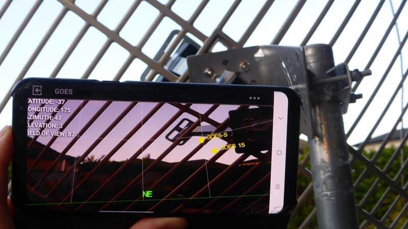
You can also use an augmented reality Android app like "Satellite-AR" to get a rough direction of the satellite. But this cannot be trusted for accuracy as the compasses on smartphones are often not very accurate. We recommend using a standard magnetic compass to help point by using the Azimuth (magn.) information from dishpointer.
Using the Satellite-AR Android App to check the rough direction of GOES-17.
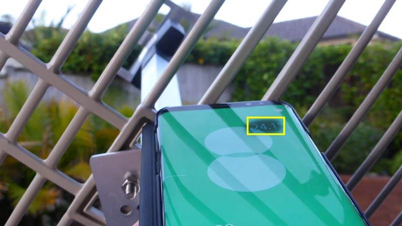
To determine the elevation you can use a bubble leveling tool, or an Android app like "Bubble Level".
NOTE: We may be slightly wrong on this polarization info as the polarization might also be dependent on the satellites's antenna oritentation. This info seems to hold true for GOES satellites, but not GK-2A. If any one can confirm, please let us know.
Once you have the Elevation and Azimuth of the dish approximately correct, you'll need to adjust the rotation (aka skew) of the dish in order to match the polarization of the satellite at your location. Dishpointer will tell you exactly what rotation angle to use, and in which direction, under the "LNB Skew" information.
If you are on the same longitude as the satellite your skew will be zero, and no rotation will be required. However, those further away on the longitude plane will require their dishes to be rotated. Most WiFi and 1.9 GHz grid dish antennas only allow you to rotate in 45 deg angle increments, so just choose the closest increment to what is given in dish finder.
In the image below Example 1 shows a user in California, pointing at GOES 16. Dishpointer shows that the required rotation is 42.2° CCW. So standing behind the antenna you would rotate the dish by 45° so that the left side is closer to the ground. Example 2 shows a user in New York pointing to GOES 16. Here the required rotation is almost zero, so no rotation is required. Keep the dish horizontal. In Example 3 the user in is Auckland, New Zealand pointing at GOES 17. Here the rotation is 44.6° CW, so the user would rotate the dish with the right side being lower.
Note that for GK-2A we found that the LNB skew given by dishpointer appears to be reversed in terms of the required rotation direction. We're not sure why, but may have something to do with the way the antenna is oriented on GK-2A.
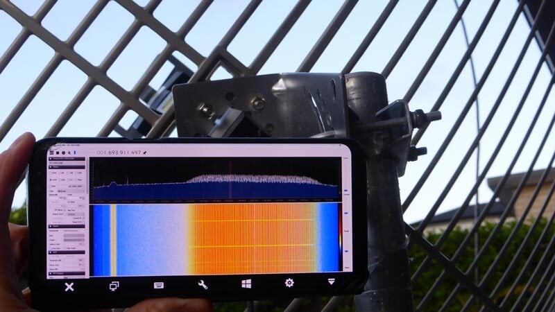
Now that you have your dish pointed in the correct direction we'll need to fine tune the positioning to detect and maximize signal strength. When fine tuning the alignment of the dish you'll need to run a program like SDR#, and keep an eye on the spectrum and waterfall while making fine adjustments to your dish. If you can't see your PC screen while positioning the antenna, it will be very difficult to confirm and tune reception.
To make it easier if you don't have a laptop, install the Teamviewer application (or any alternative like VNC) on your desktop PC, and run SDR# with the dongle and LNA connected to the antenna. Then view the PC's screen on your mobile device using the Teamviewer App, and slowly move the dish around until you see the HRIT/LRIT signal. If using the RTL-SDR V3 make sure that you activate the bias tee first using the bias tee software (see Feature 2 on the V3 guide).
Try to get the signal as strong as you can, but do not worry too much about ultra fine tuning. Later when running the software we will optimize the reception even further using the viterbi error correction rate produced by the decoder software.
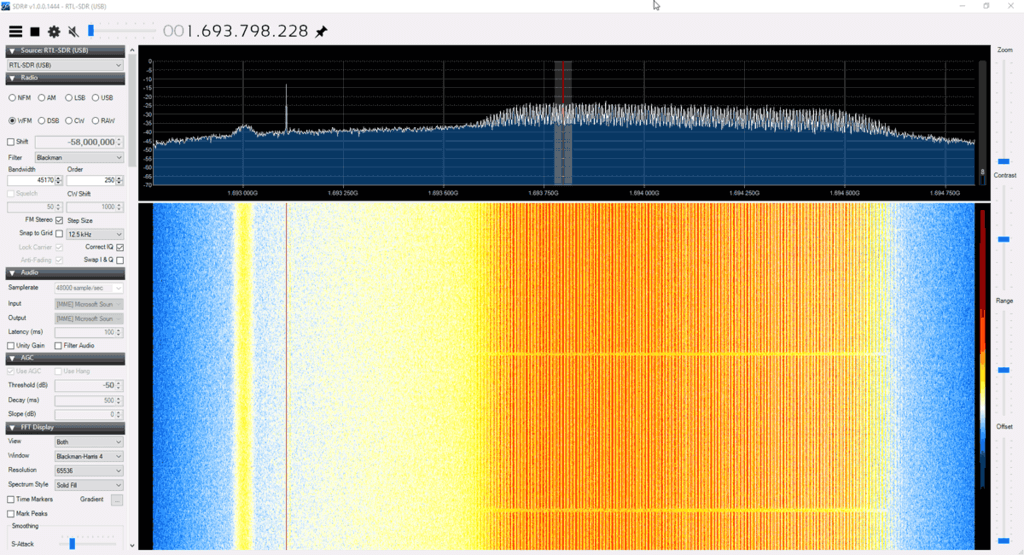
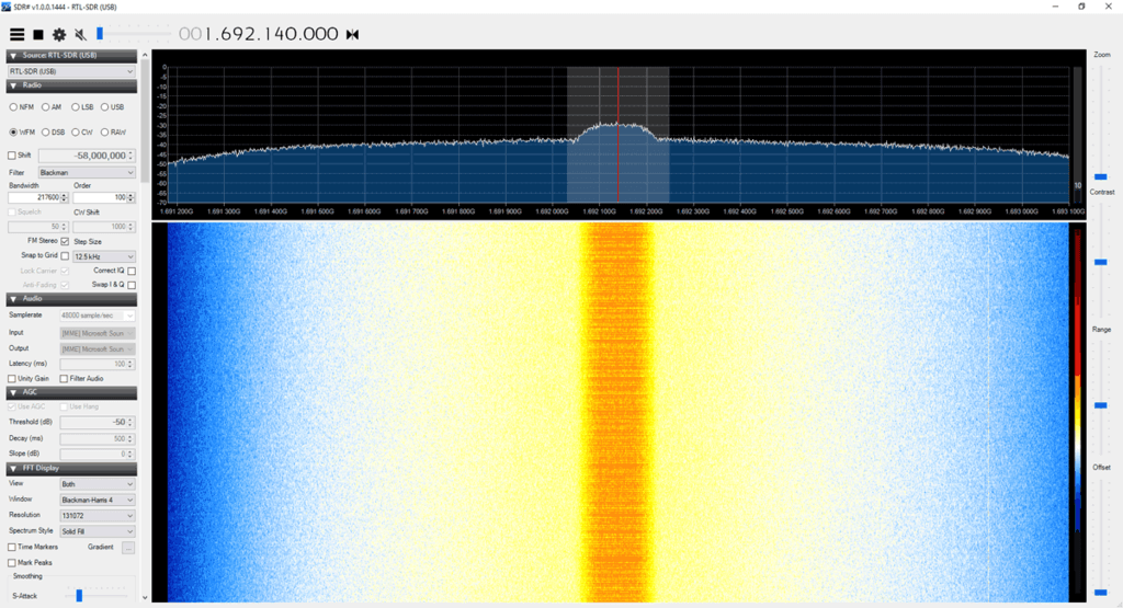
The image below shows what reception of a GOES 16/17 HRIT signal looks like. The large bump on the right is the HRIT signal which contains all the weather image data. The narrowband signal on the left is EMWIN, which contains simple text data and simple weather fax type images.
What GOES-17 looks like in SDR# on an RTL-SDRChecking GOES Reception Remotely via Teamviewer
Note that there are sometimes brief periods of a few minutes where the GOES signal is idle. During this time the HRIT signal level will be a bit lower.
The image below shows that the GK-2A LRIT signal looks like.
GK-2A LRIT Signal
Sun Interference Note: During the day time while the sun is up reception signal strength can be reduced, sometimes even resulting in no reception at all. If you cannot find the signal during the day, try again later at night after sundown. Interference appears to be the worst when the sun is behind the satellite.
When the sun is behind the satellite, we cannot receive the signal at all.
Raspberry Pi goestools Linux Software Install and Setup
For the Raspberry Pi we will use the goestools software suite which decodes and generates images for us. Goestools is made for Linux, but it might be possible to compile and run on Windows/MacOS too, although we're unaware of any successful attempts. The easiest way to set it up is to install it on a cheap Raspberry Pi 3/4.
Connect the Pi to a monitor, log in with username: pi and password: raspberry, then run "sudo raspi-config" and set up your WiFi connection.
If using an Ethernet cable you do not need to set up WiFi.
Find the IP Address of the Pi either via Method A or B
Using a monitor, open a terminal on the Pi and find it's IP address by using the command "ip addr" without quotes. Or,
Open your network routers' configuration page on any PC, and search the settings for a list of connected devices. You should be able to see the Raspberry Pi listed there, with it's IP address.
Now you should connect to your Pi from a PC on the same network using any SSH software such as PuTTy.
At this point we recommend following the excellent goesrecv software installation guidelines written by Aleksey Smolenchuk (lxe). Go through steps 1 - 6. It is a simple matter of copy and pasting the commands into the SSH terminal.
However, on step 6 of Aleksey's guide, we recommend changing the sample_rate to 2000000. We've found that higher sample rates often cause goesrecv to require multiple restarts in order to get a lock on the frequency. Also if you're using an RTL-SDR V3 enable the bias tee and increase the gain to 30:
sample_rate = 2000000
gain = 30
bias_tee = true
Running the Software and Fine Tuning the Antenna
Later we will create a script that automatically runs the software on boot. However, for now let's first test it.
To run the software open two separate SSH terminals on your main PC using PuTTy or a similar SSH terminal program. Connect to the Raspberry Pi's IP address, port: 2222 with SSH. Log into the Pi with the default username/password: pi/raspberry. In the first terminal run the command:
goesrecv -v -i 1 -c ~/goesrecv.conf
At this point you'll see a bunch of data begin to scroll by. The important thing to look at is the "vit(avg) and "drops" data. You should be seeing zero drops, and a vit(avg) of below 500, and ideally below 400. If you are seeing higher vit(avg) values and drops, you must realign and improve your dish antenna's reception. If you're getting a vit(avg) of around 400 - 600 you may be able to proceed, but some images may be lost or incomplete if you are seeing frequent drops. Anything above 600 and you probably won't be able to get any images.
Signal Optimization TIP: To further optimize the signal, install an SSH terminal like "JuiceSSH" on your mobile device. Run the above goesrecv command on your mobile, and adjust the antenna until the vit(avg) reading is as low as possible. You may need to restart goesrecv after a large adjustment for it to get a better lock on the frequency.
Remotely checking vit(avg) with JuiceSSH on Android.
Finally, if you have vit(avg) below 500 and are seeing zero drops, run the following command in the second PuTTy window.
At this point images will begin to download. Check back in 15 minutes and see what you've received. All images are written to the folder specified by the --out flag, in this case /home/pi/goes.
During testing you can easily transfer files out of the Pi to a Windows machine on the same network using a program called WinSCP. When starting WinSCP, simply select "New Site", choose the SCP file protocol and enter the Pi's IP address. You can then browse the Pi's directories, and download the image files from the folders generated in the home directory. But this is slow and time consuming, so we recommend using a more automated solution explained further below.
Also, if you wanted to, you could run goesproc on another Linux PC on your network and have the images generated on that machine. To do that, run goesproc with the Raspberry Pi's IP address in the --subscribe flag on the networked machine.
Browsing Images in a Web Browser
Note that we've had issues with Mediaweb crashing and being very slow when generating thumbnails, so we generally recommend that you use syncthing (shown below) instead.
An easier way to view the downloaded images is to install a simple folder web server like "Mediaweb" which will allow you to browse your received images on a web browser over a network connection.
Install the software using the instructions on the mediaweb Git. When installing be sure to choose /home/pi/goes as the default directory. Once installed Mediaweb will run in the background continually even after rebooting. So you can always browse your images.
Once mediaweb is installed and running, you can then browse to PI_IP_ADDR:9834 on any device connected to the same network as the Pi, and you'll be able to see the currently created folders and images (where PI_IP_ADDR is the IP Address of your Raspberry Pi).
Note that you might want to enable the thumbnail cache in /etc/mediaweb.conf, too. Remember to restart mediaweb after by using "sudo systemctl restart mediaweb".
Automatically Transferring Images to your Windows/Other Main PC
Syncthing is a program that you can use to automatically copy and sync your goes image folder with your main Windows/Mac/etc PC on the same network.
Syncthing is configured via a web interface, with default IP address of 127.0.0.1 (localhost). As we're running Raspbian Lite, we don't have a GUI and therefore can't run a web browser on the Pi. So we'll need to open the browser based configuration GUI on a networked PC. To do this we need to set the IP address of the GUI to the Pi's local network address. Edit the syncthing config, and under the <gui> entry, change the <address> value to 0.0.0.0 which will allow you to connect to the Pi's IP Address.
sudo nano /home/pi/.config/syncthing/config.xml
Syncthing config, set IP to 0.0.0.0
Save and exit with CTRL+X, Y.
Next, run "syncthing" on the command line.
Now on your main PC, open a web browser and browse to PI_IP_ADDR:8384 to open the syncthing GUI for the Raspberry Pi.
On your main PC, download, install and run the Windows version of syncthing. This will automatically open up a browser with the GUI for the Windows syncthing instance. Click on "Add Remote Device". It should be able to find the Raspberry Pi automatically, and you can double check the device ID by going to Actions->Show ID in the Raspberry Pi GUI. In the Windows GUI, simply click on the device ID, and click on Save.
Within a few seconds/minutes, the Raspberry Pi GUI should pop up with a "New Device" alert. Click on Add Device -> Save.
Still within the Raspberry PI GUI click on Add Folder. Set the folder path to /home/pi/goes, and set the label to "GOES Images". Leave the Folder ID default. Go into the "Sharing" tab, and enable sharing for your Windows machine. Click on Save.
After a few seconds/minute or two, the Windows GUI web interface should pop up with a "New Folder" alert. Click on "Add", then under "Folder Path" set where you want the image files to be copied to. Then click on save.
Wait a couple of minutes, and then it should begin syncing.
Run goesrecv, goesproc and syncthing Automatically on Boot
At the moment goesrec, goesproc and syncthing all need to be started manually whenever the Pi is rebooted. It would be better to create a system that automatically runs goesrecv, goesproc and syncthing when the Pi is booted. Then there is no need to keep an SSH terminal open and manually start the receiver and decoder whenever the Pi is rebooted.
First create two startup scripts called startgoesrecv.sh and startgoesproc.sh in your home directory.
Next create a system service that will load the script on boot, after the network service has already been loaded. We are creating two services instead of one, because we need goesrecv to start as root in order to be able to open the RTL-SDRs, and goesproc to start as user pi to make accessing the files easier later on. Also Syncthing cannot be run as root.
# Create the service to start goesrecv

sudo nano /etc/systemd/system/startgoesrecv.service

# Copy and paste the following

[Unit]
Description=Start GOES receiver after network is loaded
After=network.target
[Service]
User=root
Group=root
Type=oneshot
ExecStart=/home/pi/startgoesrecv.sh
[Install]
WantedBy=multi-user.target

# Create the service to start goesproc

sudo nano /etc/systemd/system/startgoesproc.service

# Copy and paste the following
[Unit] Description=Start GOES processor after network is loaded as user pi
After=network.target
[Service]
User=pi
Group=pi
Type=oneshot
ExecStart=/home/pi/startgoesrecv.sh
[Install] WantedBy=multi-user.target

# Create the service to start synthing
sudo nano /etc/systemd/system/startsyncthing.service

# Copy and paste the following
[Unit] Description=Start syncthing after network is loaded as user pi
After=network.target
[Service]
User=pi
Group=pi
Type=oneshot
ExecStart=/usr/bin/syncthing
[Install]
WantedBy=multi-user.target
Note that if you plan on making this a permanent station, it would be wise to connect a large external hard drive to your Pi, and save images to there. In that case you'd change the --out flag in the startgoesproc.sh to the path of the harddrive.
(Untested Idea) Even with a hard drive, you might also want to remove files and folders older than ~30 days or so to avoid running out of space. GOES16/17 transmit about 2GB of data a day so storage can run out fast. (Adjust +30 in the script below to how many number of days of images you want to keep)
The easiest way that we found was to use an online service like https://gifmaker.me. Pieterns goestools guide shows an offline Linux method involving Imagemagick, but we found it too slow to run on a Pi 3.
Then to share upload to an efficient GIF sharing site like gfycat.com.
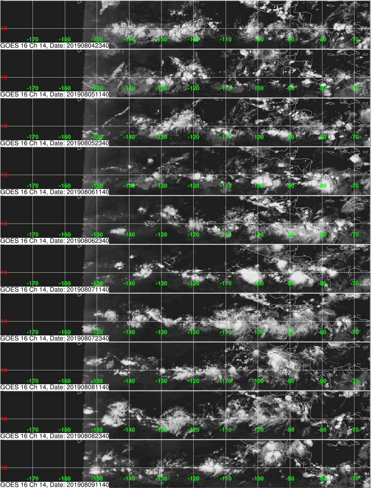
Below is a GIF of half a day of GOES 17 false color full disk images that come in every 30 minutes.
Below is a short GIF from GK-2A with 10 minute interval images.
Raspberry Pi GK-2A goestools Tutorial
Please note that GK-2A decoding is still in it's infancy, and the decoder is still being worked on by @sam210723. He is frequently updating his modified version of goestools and his xrit-rx software for GK-2A decoding.
First install the modified goestools for Gk-2A version at https://github.com/sam210723/goestools. Compilation instructions are on the page BUT we DO NOT recommendusing the apt-get install librtlsdr-dev line in his instructions, as this will most likely install an older version without bias tee support. Instead, install librtlsdr from source as explained in Aleksei's guide. If you already installed the original goestools before then you will already have the correct librtlsdr installed. But note that running sudo make install will overwrite the original GOES goestools version. If you prefer you can just run the GK-2A goesrecv program from the build/src/goesrecv folder and not run sudo make install.
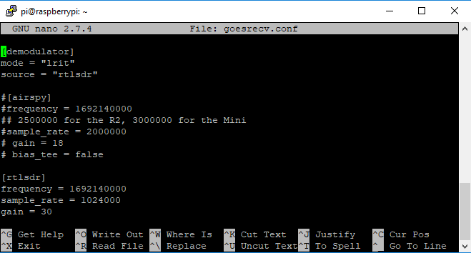
Next edit the goesrecv.conf file that you copied over with "nano goesrecv.conf". If you're using an Airspy, the conf file should already be ready, but you may want to edit it to activate the bias tee. If using an RTL-SDR, change the "source" to "rtlsdr", comment out the [airspy] settings by putting a "#" in front of them, and remove the "#" from the [rtlsdr] lines. Set the gain to 30, and bias_tee to true. CTRL+X, Y to save and exit.
Editing the goesrecv.conf file for RTL-SDR GK-2A reception.
Install xrit-rx
XRIT-RX takes the place of goesproc. First we need to download the encryption key.
You'll now have a file EncryptionKeyMessage_001F2904C905.bin.dec stored inside the xrit-rx folder. Now edit the xrit-rx.ini file with nano, and set the "keys = EncryptionKeyMessage_001F2904C905.bin.dec"
Set key file in xrit-rx.ini
Finally, open two terminal windows in PuTTy. In terminal one run the following, and confirm that you get a low vit(avg) rate, and no drops.
goesrecv -i 1 -c goesrecv.conf
In the second terminal window run the following and it will automatically begin creating LRIT files.
sh xrit-rx.sh
In order to create images from the LRIT files you need to periodically run the lrit-img.py program found in the tools folder. Once run the full disk images will be produced in the FD folder.
# Install a dependency
pip3 install pillow

# Browse to the current date
cd ~/xrit-rx/received/LRIT/20190819

# Run the program on the "FD" folder
python3 ~/xrit-rx/tools/lrit-img.py FD
Like with the standard goestools setup, you could now make these programs run on boot with systemd, and set up syncthing. You could probably also create a crontab entry to periodically run lrit-img.py.
Windows XRIT Decoder Tutorial
If you instead prefer to use Windows software, USA-Satcom (Joe) has a decoder called "XRIT Decoder". Due to certain libraries used, it is not free and is available for a price of USD $125. The price includes free future updates and access to a private groups.io forum for support and downloads.
An additional US$25 gets you an option piece of software called "XView" which is a viewer that allows you to view and filter images as they arrive. This is useful if you're creating some sort of live display. XView also has an animation feature that allows you to easily create weather movies.
XRIT-Decoder can decode GOES LRIT and HRIT data. It also appears to be somewhat compatible with GK-2A LRIT at the moment, and this is set to be improved in the future. It is compatible with the RTL-SDR, Airspy and SDRplay software defined radios.
In order to purchase XRIT-Decider you must contact him directly by email. You can also request a 30-day demo. After purchasing or requesting a demo USA-Satcom will send you activation and usage instructions.
XRIT Decoder SpyServer Setup
Note that if you are using an SDRplay SDR, you can skip this step.
For RTL-SDR and Airspy SDRs, XRIT Decoder relies on SpyServer from SDR# to provide data. SpyServer is a remote server application that supports the RTL-SDR and Airspy products. It's a part of the SDR# software package and can be downloaded from www.airspy.com.
SpyServer runs on Linux, Windows and ARM single board PCs like the Raspberry Pi. So if you wanted to you could set up a remote SpyServer on a Raspberry Pi connected directly to the antenna, and decode the data remotely on your Windows PC with XRIT Decoder.
Turn on the bias tee.
If using an RTL-SDR V3, run the V3 bias tee software and turn ON the bias tee.
If using an Airspy, edit spyserver.config with a text editor and uncomment (remove the preceeding #) the "enable_bias_tee" option in spyserver.config, and set it to '1'.
Start the SpyServer by double clicking on spyserver.exe, or running it from the command line in Linux. The default config is fine for RTL-SDRs - just remember to activate the bias tee first in step 1.
Starting and Running XRIT Decoder
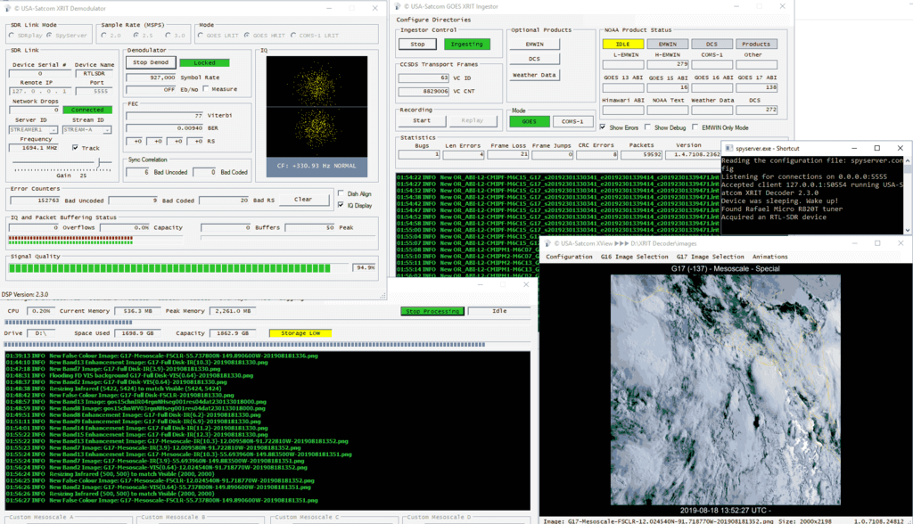
After purchasing XRIT Decoder, USA-Satcom will send you usage instructions that we won't repeat here. The basic steps are to run xrit_decoder.exe, select the SDR, sample rate and mode (LRIT/HRIT), then click on Start Demod. (For GK-2A select COMS-1 LRIT). You can then adjust the gain, and check the Viterbi rate. Like with the initial antenna setup, you can then use Teamviewer and the "Dish Align" feature in XRIT Decoder to fine tune your dish for the lowest Viterbi error rate. USA-Satcom recommends a viterbi rate of below 100, but we've found that under 400 still gives decent results.
Once your viterbi is optimized, go to the GOES XRIT Ingestor screen and click Start. Now you can open xrit_file_manager.exe, and click Start Processing in that window. Over time images will be stored in the "images" folder within the XRIT Decoder folder.
Finally, if you purchased XView, open xview.exe, and set the image path if necessary. Over time the last downloaded image will be displayed.
XRIT Decoder Screens
Example Images that You'll Receive from GOES 16/17 and GK-2A
GOES17 Full Disk False Color. Click for the full size image (14MB)Himawari 8 IR Full Disk Relay Image (Infrared) Received from GOES 17GOES 16 Full Disk Relay Received from GOES 17GK-2A LRIT IR Full Disk ImageGOES17 USA ImageNOAA AnalysisNOAA AnalysisNOAA Analysis
[mrgriscomredux] over on [Reddit] was interested in re-creating the nostalgia that was scrambled analog television from the 90s. To do this he captured an NTSC analog video signal using an RSP1 SDR and demodulated that into composite video using GNU Radio to process everything.
The methods that were originally used to scramble analog television are not well documented, however [mrgriscomredux] has done a fine job re-creating it himself in his own way.
He then uses a Python script to modify the “Gated Sync Suppression” within GNU Radio and then transmits that back on to the air using a low cost FL2K VGA adapter we’ve featured on the blog in the past.
These FL2K VGA adapters can be abused as crude software-defined transmitters and we’ve seen people do everything from video transmission to GPS spoofing with them. [Check out the FL2K article here]
Recently Chinese manufacturers have begun producing a low cost wide band (100 kHz - 30 MHz) magnetic loop HF antenna known as the MLA-30. The loop can be found on eBay for under US$45 with free shipping. In the past wide band HF loop antennas have not been cheap, normally costing $300+ dollars from manufacturers like Wellbrook.
RF signals are electromagnetic waves that consist of an electric and magnetic component. A magnetic loop antenna mostly receives the magnetic portion of the wave. This is useful as most unwanted interference from modern electronic devices is generated in the electric component only. So, a magnetic loop antenna may be preferable in city and suburban environments over other antennas like wires and miniwhips. Magnetic loops are also directional, and can be rotated to avoid interference.
One of the biggest costs to a magnetic loop antenna is the shipping, because a large hula hoop sized piece of metal needs to be sent. The MLA-30 cuts costs on shipping by providing a folded up thin loop wire and no physical support for the loop. You are expected to provide your own support, or simply hang the loop wire on something. If you like you can also replace the included loop wire with a larger loop.
The MLA-30 comes with 10m of RG174 coax, is bias tee powered, and comes as a set with a bias tee injector that is powered over 5V USB. We tested our own unit with the RTL-SDR Blog V3, Airspy and SDRplay bias tee's and found that they all worked well instead of the included bias tee. So if you have one of those SDRs using the loop is as simple and neat as plugging it in and turning on the bias tee.
In terms of build quality, the unit is sturdy and the PCB is fully potted and protected against rain/weather. It is yet to be seen how the external screw terminals holding on the loop will age over a longer period of time however.
So how does the very cheap MLA-30 compare to higher end magnetic loop antennas? Below are some reviews by various hams and SWLs. The general consensus is that it works well for the price, but as you'd expect, falters on handling very strong signals and produces a higher noise floor compared to the more expensive loops, especially in the higher HF bands. But overall we'd say that it's probably still better than using a miniwhip, especially in suburban/city environments, and is probably the best compact HF antenna that you can get on a budget.
What's included in the MLA-30 set. Photo from David Day's Review.
MLA-30 Magnetic Loop Antenna Review and Comparison by David Day (N1DAY)
In this review David compares the MLA-30 against a 30-ft ground loop and a Wellbrook ALA1530-LF. His results show that while the loop is capable of receiving the same signals that the two comparison loops can, the SNR is much lower. He also notes that the much thinner loop wire used on the MLA-30 seems to result in a much deeper null, and that IMD was a problem for him.
Inside the MLA-30 Active Loop Antenna by Matt (M0LMK)
This post is a complete teardown of the antenna. As the PCB is fully potted Matt had to boil down the epoxy in order to get to the actual PCB. He notes that the PCB is a simple single amplifier design with the exposed pot working as a gain control.
Cheap Chinese Magnetic Loop Antenna (MegaLoop aka MAGALoop) MLA-30 by John
First hour battle of the antennas W6LVP loop VS MLA 30 loop test by OfficialSWLchannel
This is a YouTube video where OfficialSWLchannel compares his MLA-30 against a W6LVP loop. He notes that his initial testing shows that the MLA-30 performs as well as the W6LVP loop.
First hour battle of the antennas W6LVP loop VS MLA 30 loop test
MLA-30 Loop vs 80M EFHW by Matthew Payne
In this YouTube video Matthew compares his MLA-30 against a 80M end fed halfwave antenna with an SDRplay RSP1a.
MLA-30 Loop vs 80M EFHW
MLA-30 Magnetic Loop Modifications by Scanner and Sdr Radio
In this video the Scanner and Sdr Radio YouTube channel uses an RSPduo to compare the MLA-30 against a Wellbrook loop. His results show that the MLA-30 definitely has a higher noise floor compared to the Wellbrook, but still receives signals decently although chasing weak signals it's not good enough. He also shows how to improve the MLA-30 by replacing the cheap coax that it comes with, noting that the modification reduced his noise.
Leif (SM5BSZ) is fairly well known in the SDR community for doing very indepth technical tests of various SDR receivers over on his YouTube channel. Recently he's released part two of a series where he compares the new Airspy HF+ Discovery against various other SDRs such as the Perseus, SDRplay RSP1, Airpsy HF+ Dual, Airspy + SpyVerter and AFEDRI SDR-Net. In the first video he studied the blocking and second order intermodulation effects of each SDR using signal generators. We summarized those results in this previous post.
In the new video Leif compares the dynamic range of each SDR using real HF antenna signals at 7.2 MHz. In order to create a fair test of dynamic range, appropriate attenuation is added to each receiver in order to make their noise figures equivalent, so that the incoming signal strength is the same for each SDR.
The first set of dynamic range results is summarized at time 08:14, and these results show the dynamic range comparisons for strong night time signals. Again like in the other videos the Perseus is used as the reference SDR since it is always the best. The tests show that the HF+ Discovery trails behind the Perseus by only -3dB, followed by the HF+ Dual at -10dB, AFEDRI at -15dB, Airspy+SpyVerter at -18dB and finally the RSP1 at -23dB.
The second set of results is summarized at 17:47 and this includes a day time dynamic range test. The rankings are very similar to the night time test.
Over on his YouTube channel icholakov has uploaded a video comparing the USB power consumption of various software defined radios. In his tests he uses an inline USB current meter and compares a Perseus, RSP1, RSP1A, Airspy HF+, Airspy HF+ Discovery, RTL V3, Nooelec RTL Mini, Hauppauge 955Q, Flightaware RTL.
If you're only interested in the summary table, then this can be found at 05:49 in the video.
Generally SDRs with better performing tuners and more amplifiers will have higher power requirements, although current consumption can't solely be used to judge performance as some SDRs like the SDRplay make extensive use of filtering to overcome RX performance issues in their tuner. The RTL-SDR V3 and FlightAware dongles have slightly higher current draw compared to the Mini RTL-SDR as they contain an additional HF amplifier and ADS-B amplifier respectively. Lower power consumption may be useful when used with batteries and mobile phones.
Nine SDR Receivers power consumption comparison - how much power does your SDR consume?
Leif (sm5bsz)'s series comparing the Airspy HF+ Discovery against various other SDRs such as the Perseus, SDRplay RSP1, Airpsy HF+ Dual, Airspy + SpyVerter and AFEDRI SDR-Net continues again, with parts 3, 4, and 5 now having been uploaded to YouTube. In previous posts we covered parts 1 and 2.
The comparisons are very technically inclined, so may be difficult to follow for those unfamiliar with radio theory. We have highlighted the time stamps where he discusses the results.
In conclusion, for all tests the Perseus always comes out on top, with the HF+ Discovery coming a close second. Generally third best is the HF+ Dual, then the AFEDRI, followed by the Airspy+SpyVerter and RSP1.
Part 3: Here performance with real antenna signals is compared. Attenuators are used to make the noise figure 26 dB of all radios at the output of the 7 port resistive splitter. This video is for dynamic range on 7.2 MHz.
Results @ 30:20
rx7compare-part3
Part 4: Here performance with real antenna signals is compared. Attenuators are used to make the noise figure 27 dB of all radios at the output of the 7 port resistive splitter. This video is for dynamic range on 14 MHz.
Results @ 16:04
rx7compare-part4
Part 5: Here here second order intermodulation is studied.
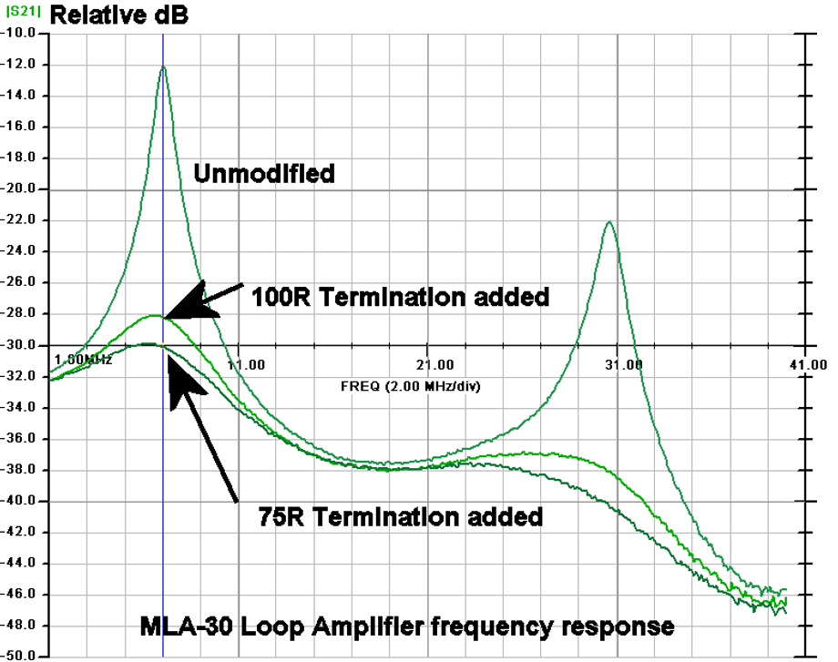
Last month we posted a collection of reviews about the MLA-30 which is a budget magnetic loop antenna designed for receiving HF signals. The overall consensus from the reviews was that it worked decently for the price, but of course could never live up to the high end loops that cost hundreds of dollars.
Recently Martin (G8JNJ) reverse engineered the active circuit used on the loop from photos taken by M0LMK and has made some observations on it's performance, noting that it's design isn't very good. First he notes that the amplifier chip is a Texas TL592B two stage video amplifier which isn't that great for this application. His measurements show an OIP3 of 20dBm, a P1 saturation of -3dBm and a noise figure of 12dB.
Of interest, he explains that the creator of this loop has designed it poorly as the impedance match of the loop to low pass filter is very wrong, resulting in a very poor amplitude/frequency response. He shows how the response can be improved with a few termination resistors, but is still not great.
MLA-30 Frequency Response. Ideally should be flat.
If you're interested in a cheap magnetic loop antenna, Martin suggests DIYing the M0AYF design which he says works a lot better.
We note that the "YouLoop" design is also in the works as a product that will apparently sell at close to manufacturing cost. The YouLoop is a passive loop idea by the creator of the Airspy that consists only of a simple 1:1 transformer and coax cable as the loop. It works best with high sensitivity radios like the HF+ Discovery.
GNU radio is a popular environment for teachers and developers involved in Digital Signal Processing and exploring new radio architectures. For receiver applications, the low cost dongle is a popular hardware choice, but if you need reliable, clean, continuous radio signal reception from 1kHz to 2 GHz (without the need for block converters or external filters) then an SDRplay RSP is a useful alternative.
With help from the GNU radio foundation, SDRplay has now made available a workflow for windows for all its RSP radios: www.sdrplay.com/docs/gr-sdrplay-workflow.pdf
Special thanks goes to Frank Werner-Krippendorf (HB9FXQ) who did the original SDRplay source block development, and to Geof Nieboer who has developed the Powershell scripts which enable operation on Windows.
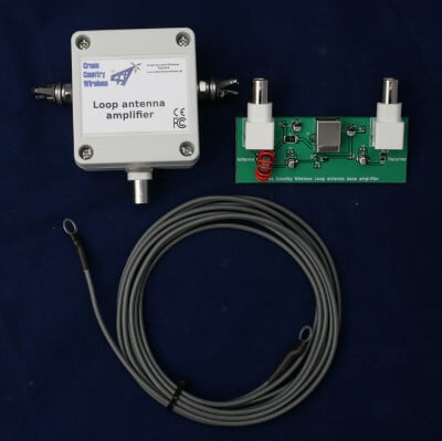
Cross Country Wireless is a UK based company that has created an active HF loop antenna for only $70 USD including international shipping. The loop appears to have already been for sale for a while now, but recently they've created a new version that can be easily powered by a 5V bias tee with at least a 67 mA current capacity. This makes it very easy to use with radios that have built in bias tee's such as our RTL-SDR Blog V3 and SDRplay and Airspy units. The page reads:
The Loop Antenna Amplifier contains all the electronics needed for home DIY construction of an active loop (magnetic loop) low noise receiving antenna.
The amplifier consists of two units, a weatherproofed outdoor unit for connection to a suitable loop and a base unit to further amplify the signal and to provide DC power up the coaxial cable to the outdoor unit.
The outdoor unit is housed in a polycarbonate box with stainless steel antenna connections and a BNC socket. The indoor unit is a PCB with two BNC connectors and a USB socket to take 5V from a USB socket on a PC or phone charger.
Like our other active antenna products it has RF overload protection to allow it to be used very close to transmit antennas without damaging the amplifier or the attached receiver.
The loop depends on what the user has available. We have tested it with simple wire loops or deltas, coax loops and an alloy loop made from a bicycle wheel rim. We supply a 3m (10 ft) length of wire as a simple loop to make a first loop for testing.
The photograph on the right shows the prototype with a 1m diameter loop of LDF4-50 coax cable as a test loop.
With a simple wire loop or delta and a small USB powerbank it makes a very compact and portable receiving antenna for holiday listening or covert use.
The latest version can now have the head unit powered directly from receivers with a 5V bias-tee such as the SDRplay receivers or some RTL-SDR dongle receivers with a bias-tee option.
Specifications:
Frequency range: 10 kHz to 30 MHz
Loop amplifier input impedance: 0.3 ohms
Output impedance: 50 ohms
Supply voltage: 5 V from USB socket or charger
Supply current (head and base unit): 112 mA
Supply current (head unit fed with 5V bias-tee): 67 mA
Loop antenna outdoor unit connectors: Two M6 stainless steel threaded studs and BNC female (RF out 50 ohms)
There is no comparison yet that we've seen on how this loop compares against the cheaper US$45 Chinese made MLA-30 loop. In a previous post Martin (G8JNJ) reviewed the MLA-30 and noted several design flaws after reverse engineering the circuit. He has let us know that he will also be reviewing the Cross Country Wireless Active Loop and will let us know his thoughts in the future.
Cross Country Wireless Loop
Cross Country Wireless Loop Antenna Amplifier VLF test with 1m diameter coax loop
Over on YouTube Mike Ladd (KD2KOG) from the SDRplay technical support team has uploaded a YouTube video showing him running our recently released RTL-SDR Blog L-Band Active Patch antenna on an SDRplay RSP1a. In the video he receives and decodes AERO signals from his car with his RSP1a powering the active patch antenna via the built in bias tee.
If you didn't already hear, we recently released an active (amplified + filtered) high performance patch antenna designed for receiving L-Band satellites such as Inmarsat, Iridium and GPS. The patch is designed to be easily mountable outside on a window, surface, stick, tree branch etc as it comes with easy to use mounting solutions and extension coax, and is enclosed in a fully weather proof plastic cover. If you're interested the product is available over on our store for US$39.95 with free shipping.
You also might want to keep an eye on Mike's YouTube channel, as he notes that in the yet to be released part 2 video he will be giving away the antenna in a competition.
SDRplay have just released their new SDR that they're calling the RSPdx. This is their new top end product which replaces the older RSP2/pro line. The RSPdx is designed for high performance DX reception and they write that it achieves this with additional filtering, improved intermodulation performance, a DAB notch filter, additional attenuation steps, and a new high dynamic range for frequencies under 2 MHz.
Pricing is £159 GBP or $199 USD (excluding taxes). It doesn't yet appear to be for purchase, but they note that it will be fully released within the next few weeks.
The RSPdx is a replacement for the highly successful RSP2 and RSP2pro SDR receivers, which have been extensively redesigned to provide enhanced performance with additional and improved pre-selection filters, improved intermodulation performance, the addition of a user selectable DAB notch filter and more software selectable attenuation steps .
The RSPdx , when used in conjunction with SDRplay’s own SDRuno software, introduces a special HDR (High Dynamic Range) mode for reception within selected bands below 2MHz. HDR mode delivers improved intermodulation performance and fewer spurious responses for those challenging bands.
The SDRplay RSPdx is a single-tuner wideband full featured 14-bit SDR which covers the entire RF spectrum from 1kHz to 2GHz giving up to 10MHz of spectrum visibility. It contains three antenna ports, two of which use SMA connectors and operate across the full 1 kHz to 2 GHz range and the third uses a BNC connector which operates up to 200MHz.
The RSPdx also features a 24 MHz ‘plug and play’ reference clock input which allows the unit to be synchronised to an external reference clock such as a GPS disciplined oscillator (GPSDO)
This is one of many video guides from SDRplay - makers of the RSP family of SDR radios. See the full list of SDRplay videos and applications documents on: https://www.sdrplay.com/apps-catalogue/
SDRplay is a UK company. The RSP SDR receivers are made in the UK and can be purchased for worldwide delivery directly from http://www.sdrplay.com/ (click on purchase and select your country to view shipping costs) or you can buy from any of our worldwide resellers listed here: http://www.sdrplay.com/distributors/ Many of the resellers offer local free shipping and/or local language technical support.
SDRplay Product Comparisons
Mike Ladd (KD2KOG) who works for SDRplay Technical services has provided the following demonstration video.
Major Announcement... The RSPdx from SDRplay.
Independent reviewer TechMinds has also uploaded a new hardware and software overview and unboxing video as well.
Over on Aliexpress and eBay there are now multiple USB2.0 extenders that work using Ethernet cable. These extenders advertise that is is possible to use up to 100m of Ethernet cable. Extending the USB connection rather than using coax cable is desirable as coax cable introduces signal losses the longer it is. Extending the digital side of the SDR (the USB cable) results in no signal being lost.
However, the USB2.0 specification notes that the maximum limit of the length of an extension cable is only 5 meters. We can go beyond 5 meters by using active repeater cables, but even this has limits of up to 30 meters maximum only.
So how can these USB2.0 Ethernet extenders advertise a length of up to 100m? These devices essentially convert the USB signal into an Ethernet network signal. Ethernet cable for network connections has a limit of 100 meters. Using this Ethernet extender is quite similar to using a Raspberry Pi and running the RTL_TCP software over an Ethernet cable, except that the network connection is handled entirely by the hardware.
We purchased a $45 USB2.0 extender from Aliexpress to test (there is also a cheaper $32 unit that we saw recently that should work too). The extender comes with a 1.5m USB Male to Male cable, a transmit box, a receive box and a 5V plug pack. The transmit side plugs into the PC via the USB Male to Male cable. The receiver end is placed up to 100m away, and this side must be powered by the 5V plug pack. In between you can run up to 100m of Ethernet CAT cabling.
USB2.0 Ethernet Extender from Aliexpress
In our testing we purchased a 50m CAT6 cable and tested to see if the extender would work with an RTL-SDR Blog V3, Airspy and SDRplay. Initially we had trouble getting SDR# to connect to the RTL-SDR. Eventually we found out that the provided USB Male to Male cable provided was of poor quality. After replacing it with a higher quality cable the extender began working properly. We also found that some USB ports on our PC wouldn't run the unit. The USB3.0 ports on the back of the PC connected directly to the motherboard worked best.
USB2.0 Ethernet Extender Test
Using SDR# the RTL-SDR Blog V3 worked exactly like it was connected directly to the PC. There was no lag noticed at all, with tuning being instant. Sample rates up to 3.2 MSPS worked fine, although of course 2.56 MSPS was the limit without drops. As the receiver box is powered by a 5V plug pack, there was plenty of power available to power a 100 mA LNA via the V3's bias tee as well.
Reliability was a bit of an issue. Sometimes we'd need to replug the USB port several times before it would connect to the RTL-SDR. But once running everything appeared to be stable, and we left it running overnight at 2.56 MSPS without any problems.
Unfortunately the lower bit rate and sample rate of the RTL-SDR appears to be the limit of what the extender can handle. The Airspy with it's higher data transfer requirements due to it's 12-bit ADC didn't work properly, with audio stuttering from dropped packets (even at the lower 3 MSPS sample rate with packing enabled). The SDRplay also wouldn't work, with the SDRUno software being unable to detect the RSP1A. Even using a shorter 2M Ethernet cable did not help for these SDRs. In theory it should work since Ethernet can support a much higher data rate, but perhaps the converter chipset used in the cheap extender unit that we have isn't fast enough.
If you want to try this out, be very careful of what you purchase on Aliexpress/eBay/Amazon. There are some very very cheap USB to Ethernet extenders out there that are advertised as USB2.0, but not all of them are truly USB2.0. The very cheap ones under $5 won't work. Those cheap units actually degrade USB2.0 down to USB1.1 which will not work for an RTL-SDR or any other common SDR. The extender units that will probably work properly are all priced over $30.
It's also possible that some of the more expensive units available on Amazon (e.g. [1][2][3]) may be implemented better and might work with the Airspy and SDRplay. If you've tried one of the pricier units please let us know in the comments if it works. In particular this $156 KVM unit which claims a high data rate and also supports PoE may work (although PoE may cause switching noise). For extreme extensions of up to 250m, USB2.0 fiber optic extenders such as this $359 unit, or this $459 fiber optic unit which can go up to 5km (3.1 miles) might also work. If you've tried any of these please let us know in the comments.
SDRplay recently released news about their upcoming RSPdx software defined radio, which replaces the RSP2 as the top of the line unit in the SDRplay lineup. The RSPdx is not yet on sale, but a few YouTube reviewers have already received their units. The first review comes from Mile Kokotov who is known to have reviewed several SDRs in the past. Mile's impressions are that the receiver works very well. He writes on his video blurb:
Today i have received the new SDR receiver from SDRplay, the RSPdx and was eager to turn it on and do some tests receiving on HF and VLF. Although at the moment my mini-whip antenna is not operational, I have connected some 20 meters wire as an antenna and start listening on VLF, LW, MW and HF...
I have to say that SDRplay team did a good job with this SDR-receiver, putting better filters and redesigning front-end to improve dynamic range and enhance overall performance in relation to its predecessors RSP2 and RSP2pro. The new RSPdx is very good indeed. Especially on HF and below.
The RSPdx has new features like HDR (High Dynamic range) mode for reception within selected bands below 2 MHz. HDR mode delivers improved intermodulation performance and less spurious responses for those challenging bands.
The New SDRplay RSPdx receiver - First Impression: Excellent!
The second review is by SevenFortyOne who runs through the various features of the SDRplay and also tests it on various HF signals.
SDRplay RSPdx Overview and SDRuno V1.33 Demo
The third video isn't exactly a review, but here TechMinds shows us how to run the RSPdx as a panadapter on his FTDX-3000.